Microgrid Architecture
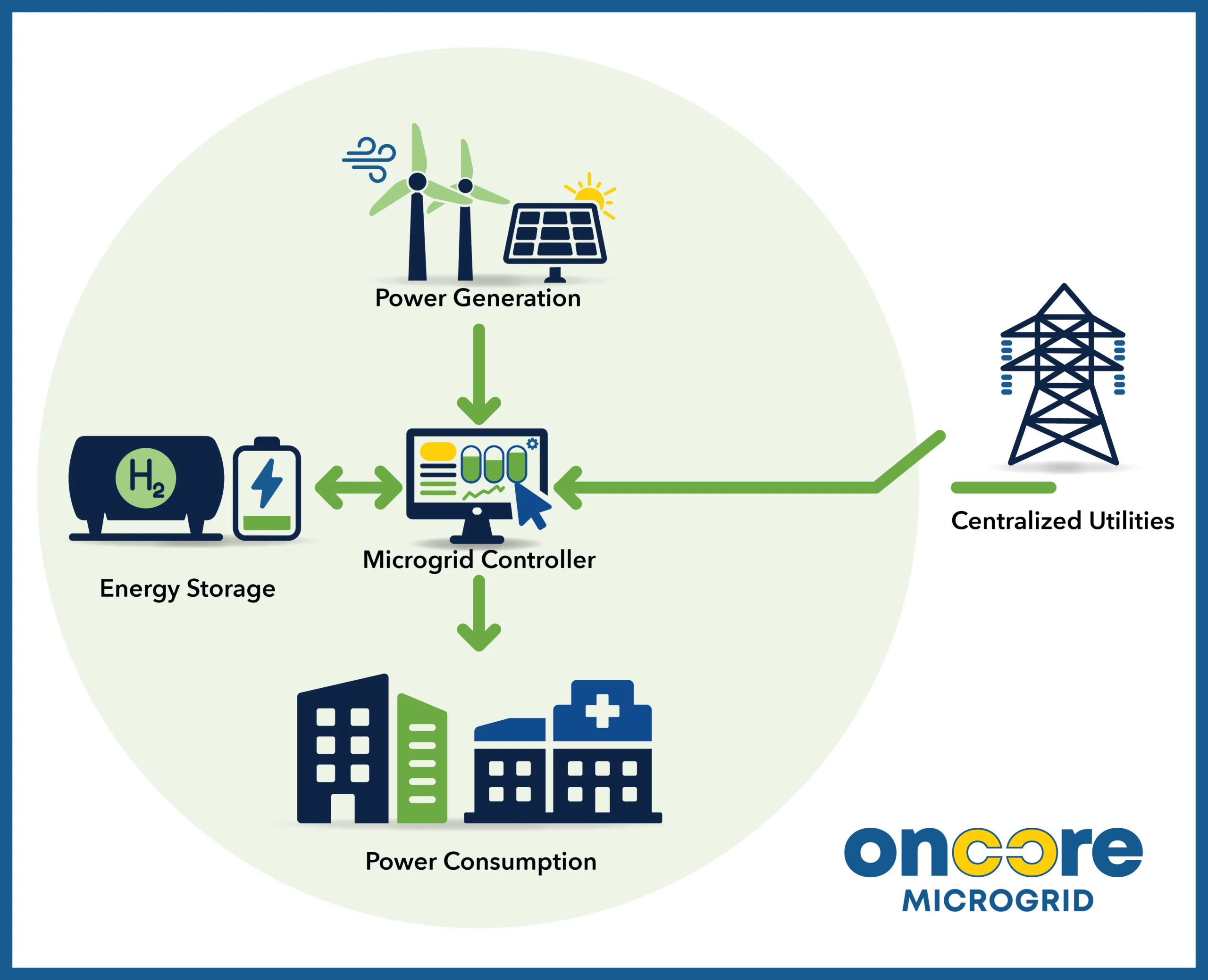
A microgrid is a self-sufficient energy system that serves a discrete local footprint - such as a home, commercial building, or factory. A microgrid may be attached to a centralized utility, but includes its own power generation and energy storage to continue operation without the utility should it become unavailable. Microgrids offer self-sufficiency, smart energy controls, high resiliency to grid outages, and the ability to reduce or eliminate emissions.
Major components include:
- Power Generation: This may be external generation from renewable sources such as solar, wind, hydroelectric, or geothermal, and also include internal sources such as the hydrogen fuel cell.
- Power Consumption: These are the factories, machines, or users that consume the electricity.
- Energy Storage: Surplus energy above and beyond what the consumers require is redirected to energy storage for later use when supplies cannot meet demand. Examples include batteries or hydrogen production via electrolysis.
- Microgrid Controller: provides essential orchestration to coordinate the flow of power between production, consumers, and efficient energy storage. This advanced software is the brains of the operation; it ensures continuous operation regardless of the status of the utility grid.
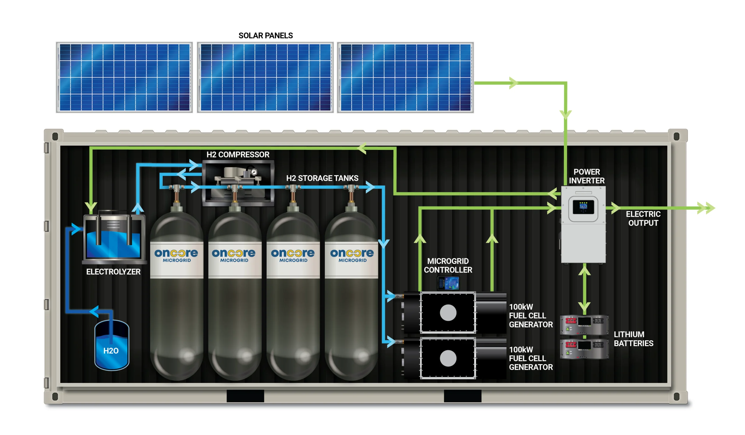
What's In the Oncore Box
Oncore Microgrid provides custom solutions to meet the end use case. Detailed engineering analysis is performed to right-size each of the major components:
- Solar Array: detailed production forecasts and array recommendations for the target location
- Fuel Cells: scale from 100 kW to 1 MW
- Battery and Hydrogen Storage: sized for backup duration (hours or days)
- Optional Electrolysis or Reformer: sized to refill the hydrogen tanks at a slow, moderate, or maximum rate
This flexibility allows us to design the optimal, right-sized solution for your requirements without over-engineering or unnecessary expense when it's not required.
Example Systems
The table below provides examples of a few reference systems. Keep in mind that the capacity of hydrogen storage and rate of hydrogen refill are all customizable - they may be optimized for performance or cost, among many other factors.
| 1 MW | 800 kW | 600 kW | 400 kW | 200 kW | 100 kW | |
|---|---|---|---|---|---|---|
| Fuel Cells (kW): | 1000 | 800 | 600 | 400 | 200 | 100 |
| Inverters (Count): | 20 | 16 | 12 | 8 | 4 | 2 |
| Electrolyzer (kg/Day): | 750 | 600 | 450 | 300 | 150 | 75 |
| Tanks (kg): | 1000 | 800 | 600 | 400 | 200 | 100 |
| Auto-Transfer: | msecs | msecs | msecs | msecs | msecs | msecs |
| Backup at 66% Load: | 24 h | 24 h | 24 h | 24 h | 24 h | 24 h |
| Refill H2: | 32 h | 32 h | 32 h | 32 h | 32 h | 32 h |
| Live Telemetry & Diag: | ||||||
| Use Cases: | ||||||
| - Backup Power | ||||||
| - Energy Arbitrage | ||||||
| - Curtailed Solar | ||||||
| - ESG |
Modular Building Blocks
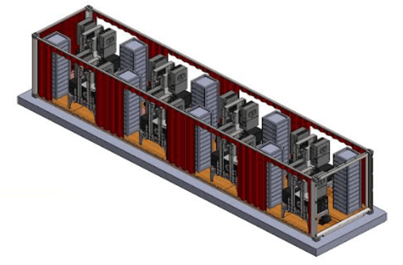
Our engineering philosophy is to design scalable blocks of power that may be stacked to achieve the desired performance (kW - MW). This approach has several advantages:
- Engineering focus on one assembly
- Optimized manufacturing
- Parts commonality and service procedures
- Simplified software development
- Better quality control
When stacked together into a modular system, the resulting architecture has several advantages over legacy fossil fuel generators:
- Highly resilient with multiple levels of tiered redundancy
- Self-healing around faults without performance degradation
- Online parts replacement without service interruption
- Highly scalable architecture with minimal engineering rework
- Rotating preventative maintenance during continuous operation


